1769-CRL3 Cable Length: Maximum Distance and Layout Guide
Mastering the 1769-CRL3 Expansion Cable: Distance Limits and System Reliability
The maximum length for a 1769-CRL3 expansion cable is exactly 3 meters (approximately 9.8 feet).
This limit is a fixed electrical boundary defined by the CompactLogix 1769 bus specifications.
At PLCDCS HUB, we view this cable as a vital tool for optimizing complex panel layouts.
However, pushing beyond this distance compromises the industrial automation system’s deterministic communication.
This guide explores why respecting this 3-meter limit is non-negotiable for professional control systems.
Strategic Value of Local Bus Expansion
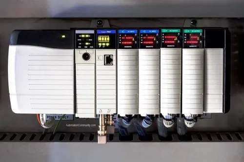
The 1769-CRL3 allows you to split I/O modules into separate banks within a single cabinet.
This flexibility is essential for oil and gas skids or pharmaceutical process plants with tight spaces.
Unlike remote I/O, this cable extends the local backplane without adding network configuration overhead.
Therefore, you maintain high-speed communication while physically distributing your hardware.
Our engineers suggest using this method to reduce complex wiring runs between PLC components.
Technical Constraints of the 3-Meter Limit
The 1769 local bus operates with extremely tight signal timing and integrity requirements.
Exceeding the 3-meter threshold often leads to spontaneous major faults during power cycles.
Moreover, you might encounter random module recognition failures that are difficult to diagnose.
Rockwell Automation designs these cables to prevent signal attenuation over the bus.
As a result, attempting to extend this cable with third-party adapters will likely cause system crashes.
Deterministic behavior is only guaranteed when you stay within the factory-defined distance.
Environmental Sensitivity and Shielding Best Practices
While the 1769-CRL3 is robust, it remains sensitive to electromagnetic interference (EMI).
Routing this cable next to high-voltage motor leads often triggers sporadic I/O connection losses.
In addition, physical vibration on stamping machines can loosen the bus connectors over time.
Always treat the expansion cable as a critical backplane extension rather than a standard control wire.
Proper routing and mechanical securing are mandatory to ensure long-term factory automation stability.
Field Installation and Maintenance Procedures
Field success depends on strict adherence to installation discipline and hardware safety.
Based on our experience at PLCDCS HUB, most cable failures stem from improper handling during commissioning.
Always power down the entire rack before connecting or disconnecting the 1769-CRL3.
Hot-plugging these cables can cause permanent damage to the sensitive bus pins.
Maintaining clean, secure connections is the easiest way to avoid “ghost” faults on the production floor.
- ✅ Secure both connectors with rigid strain relief within 100 mm of the module.
- ✅ Maintain at least 200 mm of separation from VFD or motor power cables.
- ✅ Cross power cables at a 90-degree angle if parallel routing is impossible.
- ✅ Verify that the total I/O count per bank stays within power supply limits.
- ✅ Inspect connectors for bent pins before every installation attempt.
- ✅ Use only genuine 1784 or 1769 series expansion hardware for reliability.
Author Insight: Perspectives from PLCDCS HUB
At PLCDCS HUB, we have seen integrators try to daisy-chain multiple CRL3 cables.
This practice invariably leads to timing violations and project delays during SAT (Site Acceptance Testing).
If your layout requires more than 3 meters, you must transition to EtherNet/IP remote I/O.
Modernizing with POINT I/O or FLEX 5000 is a better long-term strategy for distributed control.
Treating the 3-meter limit as a hard boundary protects both your equipment and your reputation.
Do you need a 1769-CRL3 cable or expert advice on I/O bank configuration? Visit
PLCDCS HUB Limited
for authentic parts and professional technical support.
Application Scenarios and Solutions
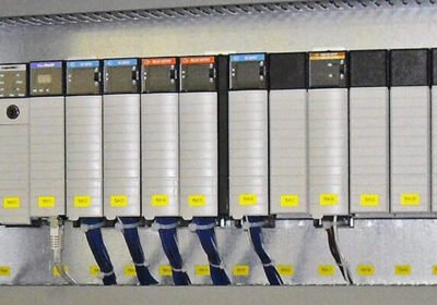
Scenario: A manufacturing cell needs to split 16 modules into two rows of 8 to fit a shallow enclosure.
Solution: Use one 1769-CRL3 cable to link the right end of the first bank to the left end of the second.
This maintains local bus speed while effectively doubling the vertical mounting space.
Frequently Asked Questions (FAQ)
1. Can I use a 1769-CRL1 (1 meter) and a 1769-CRL3 together?
No. The 1769 architecture only supports one expansion cable per transition between I/O banks.
You cannot combine cables to increase length, as this violates the bus timing requirements.
2. When should I switch from expansion cables to remote I/O?
If your I/O bank is further than 3 meters away or located in a separate room, use remote I/O.
EtherNet/IP adapters like the 1734-AENTR are better suited for long-distance distributed control.
3. Does the 1769-CRL3 cable require a separate power supply for the second bank?
Yes. Most 1769 expansion configurations require a separate 1769-PA2 or PB2 power supply for the second bank.
The cable carries bus signals but does not typically provide enough current for multiple high-load modules.


No Comments