
1769-L33ER I/O Recognition Issues: Fixing 1769-IQ32 Bus Errors
Solving 1769-L33ER Recognition Failures with High-Density 1769-IQ32 Modules
Engineers often encounter a frustrating scenario where a 1769-L33ER controller fails to recognize the final I/O module.
The software configuration in Studio 5000 appears correct, yet the hardware remains invisible to the backplane.
At PLCDCS HUB, we frequently identify local bus length and power limitations as the primary root causes.
This guide explains the physical constraints of industrial automation hardware that lead to these commissioning hurdles.
The Strategic Importance of Bus Power Management
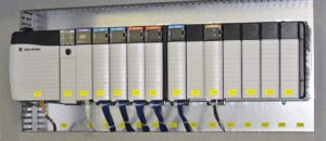
The Allen-Bradley 1769 CompactLogix platform provides a reliable solution for high-density factory automation.
It integrates processing and I/O into a single, compact footprint suitable for oil, gas, and pharmaceutical plants.
However, the system relies on a delicate balance of backplane current and signal integrity.
Ignoring these electrical constraints can silently undermine your control systems during high-demand operations.
Therefore, understanding the physical limits of the 1769 bus is essential for long-term reliability.
Local Bus Current Budgets and Power Consumption
The 1769-L33ER controller provides a finite amount of current to the attached 1769 I/O modules.
High-density modules like the 1769-IQ32 draw significantly more power than standard 16-point digital cards.
When the total current exceeds the controller’s capacity, the furthest module usually fails to initialize.
This issue often presents as an intermittent fault or a missing module error after a power cycle.
As a result, the last module on the rail lacks the necessary voltage for stable communication.
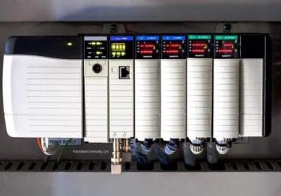
Physical Bus Length and Signal Degradation
CompactLogix systems use direct mechanical connectors rather than a passive powered backplane.
Each added module increases electrical loading and introduces a minor signal delay across the bus.
End-of-line modules are naturally the most sensitive to these marginal electrical conditions.
Moreover, cumulative impedance from multiple high-density cards can degrade communication pulses.
Even if the software accepts the rack size, hardware physics will eventually dictate the system’s success.
Installation Best Practices and Field-Proven Advice
Maintaining system stability requires proactive planning during the hardware layout phase.
Based on our experience at PLCDCS HUB, simple mechanical adjustments often resolve complex communication errors.
We recommend placing the most power-intensive modules immediately adjacent to the controller or power supply.
Furthermore, always verify the locking tab engagement to ensure maximum surface contact between the bus connectors.
- ✅ Recalculate the total bus current when adding high-density 32-point modules.
- ✅ Use a 1769 expansion power supply to segment long I/O racks.
- ✅ Place high-current 1769-IQ32 modules as close to the CPU as possible.
- ✅ Check DIN rail alignment to prevent mechanical stress on bus connectors.
- ✅ Re-seat the end-cap terminator if the last module is inconsistent.
- ✅ Monitor backplane voltage during peak I/O activity for potential drops.
Author Insight: Perspectives from PLCDCS HUB
We often see retrofits fail because teams add “just one more card” without checking the power budget.
Modern PLC systems require more than just logic; they require strict adherence to electrical specifications.
At PLCDCS HUB, we advise using remote Ethernet I/O adapters for racks exceeding eight modules.
This strategy offloads the local bus and improves the overall responsiveness of your industrial automation network.
Looking for reliable replacement parts or technical support for your CompactLogix system?
Visit PLCDCS HUB Limited
to browse our inventory of authentic Allen-Bradley controllers and I/O modules.
Application Scenario: Packaging Line Expansion
A high-speed bottling plant recently expanded its conveyor control by adding three 1769-IQ32 modules.
Initially, the 1769-L33ER failed to detect the final input card, causing a system-wide interlock fault.
After our team installed a 1769-PA2 expansion power supply, the bus voltage stabilized.
The controller recognized the modules immediately, and the line achieved its target throughput without further errors.
Frequently Asked Questions (FAQ)
1. Why does the L33ER only fail to see the last module?
The last module is furthest from the power source and communication clock.
Voltage drops and signal reflections are most severe at the physical end of the bus.
If the current budget is tight, the last module receives the least amount of stable power.
2. Is there a maximum number of modules for a 1769-L33ER?
The L33ER supports up to 16 local I/O modules across three banks.
However, using high-density cards like the 1769-IQ32 reduces this practical limit per bank.
You must consult the Rockwell Automation “Power Supply Distance Rating” for each specific module.
3. What are the symptoms of a failing 1769 bus connection?
Common signs include yellow exclamation marks in Studio 5000 and “Module Not Found” errors.
In some cases, the I/O data may intermittently freeze or report random values.
Always check the physical bus locking tabs first when these symptoms appear in the field.


No Comments