Bently Nevada 176449-02 Wiring: Expansion vs. Vibration Guide
Understanding Bently Nevada 176449-02 Rear I/O Module Wiring
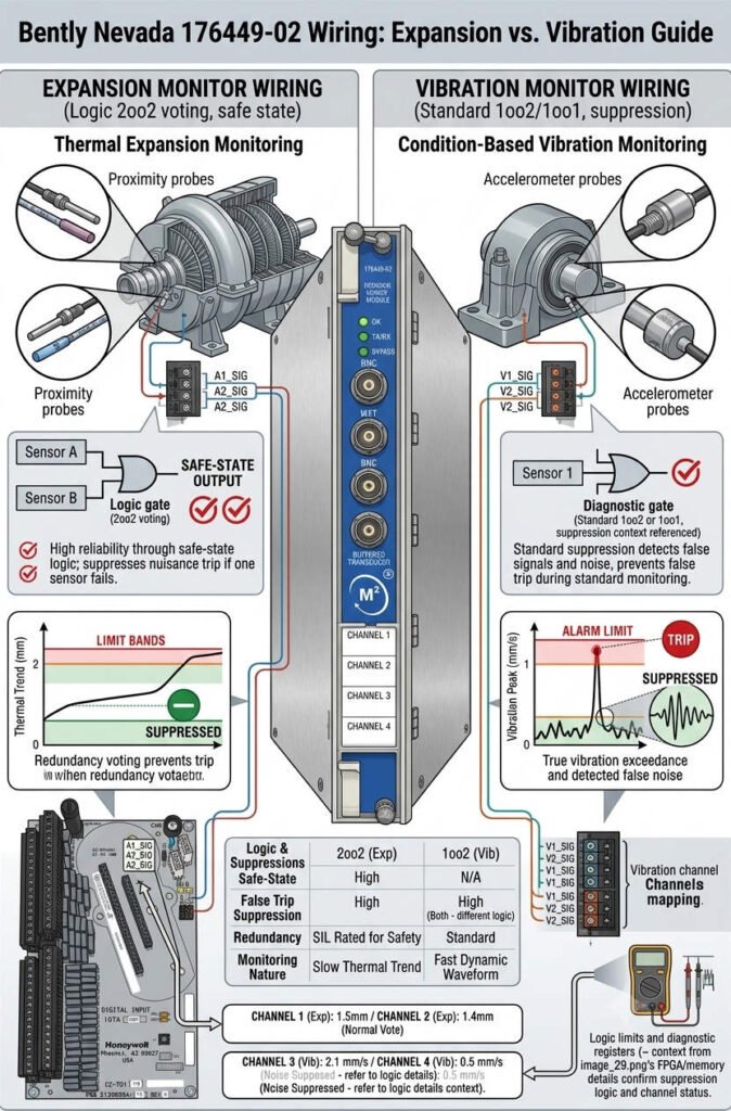
The Bently Nevada 176449-02 serves as a critical interface for the 3500/45 Differential Expansion Monitor. In industrial automation, precision is non-negotiable. Whether you are managing power generation or petrochemical assets, incorrect wiring leads to false alarms or catastrophic machinery failure. This guide clarifies the specific terminal differences between differential expansion and radial vibration setups to ensure your control systems remain robust and reliable.
Understanding Differential Expansion Configuration
Differential expansion measures the thermal growth between a turbine rotor and its casing. The 176449-02 module receives signals from two distinct probes, often labeled Probe A and Probe B. The internal monitor logic performs a subtraction calculation to determine the relative axial displacement.
- Use two reference probes for accurate delta calculation.
- Verify the physical mounting direction against software settings.
- Ensure shielding is grounded at only one termination point.
- Monitor cold-start versus hot-run baseline values closely.
Differentiating Radial Vibration Monitoring
Radial vibration monitoring treats every sensor as an independent entity. You typically install X and Y probes to capture shaft orbit data. Unlike the expansion configuration, the 176449-02 module does not perform internal mathematical operations between these specific channels. Each signal path remains isolated to preserve the integrity of the vibration waveform.
- Configure channels for direct amplitude measurement.
- Maintain clear separation between X and Y signal wires.
- Avoid mixing vibration probes with expansion calculation logic.
- Use dedicated shield drains for each independent sensor pair.
Engineering Insights: Avoiding Common Commissioning Errors
Based on our experience at PLCDCS HUB, the most frequent issue involves the 176449-02 Internal Barrier module. Technicians often confuse the reference direction of A and B probes. Even if the wiring polarity is correct, reversing the physical orientation causes the expansion trend to invert. This error often stays hidden until the turbine heats up, potentially leading to dangerous operational decisions.
Furthermore, electromagnetic interference remains a silent killer of signal accuracy. Always route probe cables away from high-power VFD lines or motor feeders. If you require expert guidance on hardware selection or system integration, visit PLCDCS HUB for professional resources and technical support.
Practical Application: Solution Scenarios
When upgrading older 3500 rack systems, ensure your firmware version supports the 176449-02 module specifications. Incompatibility often arises when legacy hardware encounters modern high-density I/O modules. Always consult the latest API 670 standards to align your machinery protection strategy with industry best practices.
Frequently Asked Questions
- How do I confirm if my 176449-02 module is wired correctly for expansion?
Perform a manual shaft movement test during commissioning. If the software output does not match the physical direction of the rotor growth, swap the A and B probe inputs or reconfigure the software polarity settings. - Can I use the same I/O module for both vibration and expansion?
While the physical 176449-02 module may fit in the slot, the configuration logic differs. Never assume that a module pre-configured for radial vibration will function correctly for differential expansion without a full review of the channel programming. - What is the best way to prevent drift in low-level signals?
Ensure high-quality shielding and isolate probe wiring from all high-voltage cabling. Consistent grounding at the rack side is essential to prevent ground loops that mimic thermal expansion noise.