Fast Circuit Breaker Trip Identification in DCS Systems
How to Rapidly Identify Circuit Breaker Trip Points in DCS Systems
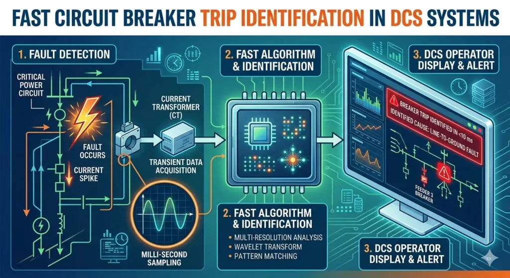
Unexpected circuit breaker trips in a Distributed Control System (DCS) cause expensive downtime. In oil and gas or chemical processing, every minute of interruption impacts the bottom line. Therefore, engineers must use a structured diagnostic approach to isolate faults. Quickly locating the trip point prevents cascading failures across complex control loops.
Effective fault detection minimizes process disturbances and improves overall plant safety. At PLCDCS HUB, we believe that modern diagnostic tools are essential for maintaining high-availability power distribution architectures.
Leveraging High-Resolution Sequence of Events (SOE) Logging
Accurate time synchronization is the most critical factor for identifying the root cause of a trip. High-resolution SOE logging typically records events at a 1 ms interval. Without synchronized clocks (NTP or IRIG-B), event logs can become misleading and confusing.
- ✅ Synchronize all controllers to a master clock source.
- ✅ Verify that SOE cards support sub-millisecond resolution.
- ✅ Analyze timestamps to distinguish primary faults from secondary trips.
Precise event data reduces the Mean Time to Repair (MTTR) significantly. When multiple breakers trip simultaneously, the sequence tells you exactly which device failed first.
Integrating Intelligent Protection Relays via IEC 61850
Modern industrial automation relies on smart communication between the DCS and protection relays. Protocols like IEC 61850 or Modbus TCP provide deep diagnostic visibility. Unlike old hardwired systems, these protocols capture fault types and waveforms.
Using IEC 61850 GOOSE messaging allows for trip indications in less than 4 ms. This speed enables the control system to react before a minor electrical issue becomes a site-wide blackout. We highly recommend upgrading legacy serial links to high-speed Ethernet-based communication for better data transparency.
Optimizing Alarm Management and Prioritization
Operator overload often delays fault response during a major electrical event. A well-rationalized alarm system follows standards like ISA 18.2 or EEMUA 191. Proper prioritization ensures that critical breaker trips stand out among nuisance alerts.
- ⚙️ Classify breaker alarms as high priority in the HMI.
- ⚙️ Implement alarm shelving for non-critical secondary notifications.
- ⚙️ Group related power alarms to simplify the operator’s view.
Effective alarm management reduces the cognitive load on plant personnel. Consequently, they can identify and resolve the power fault much faster during an emergency.
Best Practices for Installation and Maintenance
Field experience shows that minor wiring errors often lead to major diagnostic headaches. Misalignment between auxiliary contacts and DCS input points causes false trip reports. Always perform thorough point-to-point loop checks during commissioning.
- 🔧 Verify NO/NC logic settings in the DCS database.
- 🔧 Install surge protection devices (SPD) on control power lines.
- 🔧 Use isolated power supplies for all trip coil circuits.
Stable control voltage is vital for reliable breaker operation. Voltage dips or noise can trigger intermittent trips that are difficult to replicate. Protective shielding in high-noise environments prevents these “phantom” events.
Author Insight: The Future of Power Diagnostics
From the perspective of PLCDCS HUB, the industry is moving toward predictive power monitoring. Simply knowing “when” a breaker tripped is no longer enough. Modern systems now analyze current signatures to predict a trip before it occurs. If you are managing an older facility, consider a hybrid approach by adding gateways to extract relay data.
Need high-quality DCS modules or communication interfaces? Visit PLCDCS HUB Limited to find the right hardware for your system upgrades.
Application Scenario: Pharmaceutical Clean Room Power
In a pharmaceutical facility, even a brief power loss ruins expensive batches. By implementing redundant voltage monitoring upstream of the main breakers, the DCS can differentiate between a utility failure and a local equipment fault. This allows the system to switch to UPS power automatically while flagging the specific breaker for inspection.
Frequently Asked Questions
How can I improve trip diagnostics on a legacy DCS with limited I/O?
Instead of adding more hardwired cables, install a Modbus TCP or IEC 61850 gateway. This extracts detailed fault data from existing protection relays and feeds it into your DCS over a single network cable.
What is the most common reason for a “false” trip indication?
Inverted logic (Normally Open vs. Normally Closed) is the leading cause. Always cross-check your field wiring against the software logic during the Site Acceptance Test (SAT).
Should I prioritize SOE resolution or network bandwidth?
For electrical faults, SOE resolution is more important. A 1 ms resolution is the industry standard for power diagnostics. Ensure your network can handle the bursts of data during a major fault event without dropping packets.
Related Posts


No Comments