
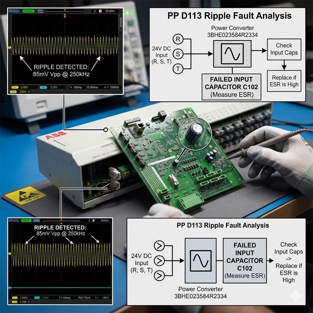
Troubleshooting ABB GF D233 3BHE022294R0101 Initialization Faults
ABB GF D233 3BHE022294R0101 ERR LED Blinks 3 Times: Troubleshooting Guide
The ABB GF D233 3BHE022294R0101 interface board provides crucial data linking within ABB excitation and drive control systems. When the specialized “ERR” LED flashes 3 times repeatedly, it indicates a communication initialization or synchronization failure. In the industrial automation sector, this fault code typically appears during startup commissioning or after power disturbances. Ignoring this diagnostic blink code can lead to unstable excitation regulation or controller redundancy switchover failures. Therefore, maintenance teams must diagnose the root cause quickly to prevent unexpected plant downtime.
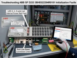
Decoding the 3-Blink ERR LED Diagnostic Pattern
On ABB GF-series boards, the onboard firmware drives the “ERR” LED as a precise status indicator. A repeating pattern of 3 flashes followed by a brief pause signifies an FPGA or DSP initialization timeout. Moreover, a fieldbus handshake failure or invalid backplane communication can trigger this specific error pattern. This state frequently points to oxidized rack connectors or an unstable auxiliary power supply during bootup sequences. Consequently, the interface board fails to establish a deterministic timing connection with the parent controller hardware.
Expert Insight from PLCDCS HUB: Many field engineers assume a 3-blink error code means the board is permanently dead. However, we often find that a firmware mismatch between the CPU and the GF D233 causes this lockout. At PLCDCS HUB, we recommend verifying software compatibility matrices before ordering an entirely new replacement board for your control systems.
The Impact of Power Quality and Startup Voltage Dips
The GF D233 interface board is highly sensitive to transient undervoltage conditions during its initial boot sequence. In older substations, aging UPS batteries or excessive DC ripple can compromise the 24VDC control power. Static measurements with a standard multimeter often fail to capture millisecond-level voltage dips during startup. Therefore, engineers should utilize an oscilloscope to monitor power stability under full rack load conditions. Maintaining clean power according to standard EMC recommendations significantly reduces intermittent initialization alarms in factory automation hubs.
Navigating Communication Bus and Firmware Compatibility
Matching the part number 3BHE022294R0101 is sometimes insufficient when sourcing parts for mixed-generation systems. If replacement boards contain older firmware, they may reject updated protocol revision tables from newer PLC units. This incompatibility alters watchdog timing parameters, resulting in immediate initialization lockouts upon power-up. Thus, engineers must verify both the hardware revision suffix and the firmware package level before field deployment. In continuous-process plants, validating database compatibility prevents costly retrofitting delays during emergency turnarounds.
Technical Field Procedures for Maintenance Teams
Resolving persistent synchronization alarms requires a structured approach to mechanical and electrical cabinet maintenance. Technicians should execute the following technical steps:
- ✅ Inspect Backplane: Check for gold finger oxidation and clean the contacts using approved chemical solvents.
- ✅ Verify Clip Tension: Ensure all rack retention clips lock firmly to resist heavy cabinet vibration.
- ✅ Analyze Power Waves: Measure the 24VDC startup waveform with an oscilloscope to catch transient voltage drops.
- ✅ Avoid Hot Swapping: Disable control power before inserting the board unless the system documentation explicitly permits live replacement.
Procurement Strategy: Repairing vs. Replacing Your Board
If the 3-blink ERR pattern disappears after cleaning connectors or stabilizing power, the hardware itself remains functional. However, if the error persists across multiple racks, the internal communication circuitry has likely degraded. Replacing the module becomes necessary when onboard diagnostic circuits fail to complete their baseline power-on self-tests. When buying a replacement, work with an experienced vendor to guarantee correct firmware alignment. This step ensures that your new component integrates seamlessly into your existing DCS network topology.
Application Scenarios and Solutions
- Thermal Power Plants: Eliminates unstable thyristor firing units by correcting millisecond-level startup voltage dips.
- Petrochemical Pumping Stations: Resolves intermittent I/O response delays caused by micro-movements in high-vibration cabinets.
- Heavy Rolling Mills: Restores reliable controller tracking by upgrading mismatched board firmware during scheduled maintenance windows.
For fully certified ABB modules and expert hardware diagnostic services, visit PLCDCS HUB Limited today. We supply the genuine components and technical support required to keep your systems running smoothly.
Frequently Asked Questions (FAQ)
1. Why does my GF D233 board show the 3-blink error only during cold restarts?
This symptom points directly to a transient power dip or an aging capacitor on the power line. The board fails to initialize because the voltage drops below the baseline threshold during the initial current rush.
2. Can a loose ground wire inside the cabinet cause this initialization fault?
Yes, poor grounding introduces electromagnetic noise into the communication bus. This noise disrupts the initialization handshake between the board and the controller, triggering the error code.
3. How can I determine the exact firmware version pre-loaded onto my replacement board?
You must read the barcode label suffix or connect the board to an ABB diagnostic terminal. Matching this suffix with your controller documentation ensures total communication compatibility.