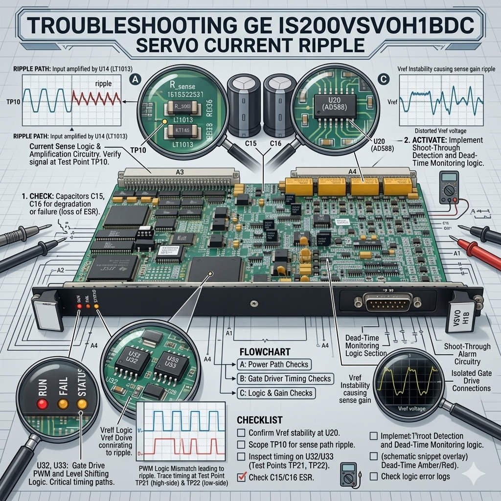
GE IS200VSVOH1BDC Servo Board: Fix Moog Valve Oscillation
Troubleshooting Moog Servo Valve Oscillation on GE IS200VSVOH1BDC Output Boards
The GE IS200VSVOH1BDC servo output board drives critical electro-hydraulic servo valves, such as Moog valves, within Mark VI and EX2100 control systems. When a servo valve exhibits continuous jitter or high-frequency spool oscillation, engineers often suspect excessive output current ripple. While unwanted AC components do cause stability issues, the actual root cause usually involves more complex system dynamics. In large power generation and petrochemical facilities, diagnosing this erratic behavior accurately prevents costly turbine mechanical fatigue and sudden load hunting events.
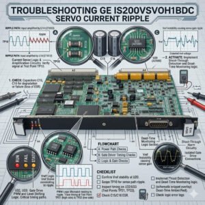
Analyzing Servo Output Current Ripple and Its Operational Impact
The output stage of the GE IS200VSVOH1BDC generates a precise, DC-controlled proportional current signal to position hydraulic actuators. However, component degradation or loose power supply filtering can introduce harmful AC ripple into the primary regulation loop. If this superimposed ripple exceeds 10% of the nominal current value, noticeable Moog valve vibration occurs immediately. Over time, high-frequency oscillations generate excessive heat inside the torque motor coils and accelerate flapper-nozzle wear. Therefore, checking the raw current waveform helps avoid premature and unnecessary valve replacements.
Expert Insight from PLCDCS HUB: Field technicians frequently replace expensive Moog valves only to find the oscillation persists. At PLCDCS HUB, we emphasize that a servo valve is merely an execution device. If the driving electronics deliver a noisy current signal, even a brand-new valve will vibrate violently. Always verify the signal integrity before condemning the mechanical hardware.
Evaluating Feedback Loop Stability and Actuator Hydraulic Resonance
A closed-loop control system integrates the servo board, hydraulic actuator, LVDT position feedback, and core turbine algorithms. Consequently, changes in hydraulic damping can cause severe loop instability even when the electronic board functions perfectly. Severe oil contamination, internal cylinder leakage, or entrained air bubbles alter the dynamic response of the fluid. This physical degradation creates cyclic feedback oscillations that look identical to an electrical failure. Maintenance teams must evaluate hydraulic oil health alongside electrical loops to locate the true fault source.
Mitigating Grounding and Shielding Issues in Factory Automation
High-noise plant environments can introduce severe common-mode interference into sensitive analog loops through inadequate cabinet grounding structures. The GE IS200VSVOH1BDC board requires strict shielding continuity to protect its low-voltage current drivers from adjacent high-power equipment. Improperly terminated cable shields often capture transient electromagnetic noise from variable frequency drives (VFD). To maintain stable data highways, engineers must enforce single-point shield grounding and isolate analog signal routing ducts completely. Correcting basic termination mistakes frequently eliminates stubborn servo jitter without changing expensive modules.
Field-Proven Calibration and Oscilloscope Maintenance Protocols
Isolating erratic servo valve behavior requires a methodical, hands-on diagnostic approach. Field maintenance teams should utilize the following technical protocols:
- ✅ Waveform Inspection: Measure actual current signals with a differential oscilloscope probe rather than relying on DCS trends.
- ✅ Oil Quality Assurance: Verify the hydraulic fluid matches strict NAS cleanliness standards to rule out sticky valve spools.
- ✅ Terminal Torque Verification: Re-tighten all terminal blocks during scheduled outages to counteract constant turbine structural vibrations.
- ✅ Ground Loop Evaluation: Test the cabinet earth resistance value to confirm no stray AC voltages compromise the board.
Strategic Procurement and Hardware Revision Matching Guidelines
Only consider a replacement board after confirming that the current waveform stays distorted under known-good jumper tests. Backward compatibility across different DCS generations depends heavily on specific firmware revisions, control constants, and board suffix codes. Installing a mismatched revision without updating the turbine application database can introduce permanent control loop errors. Buyers must cross-reference their exact system parameters against official GE compatibility matrixes. Conducting loop validation testing before full commissioning ensures safe and reliable PLC and servo tracking.
Application Scenarios and Solutions
- Steam Turbine EH Systems: Eliminates persistent valve hunting by replacing aged power supply filtering capacitors on the board.
- Gas Turbine Fuel Regulators: Cures severe high-frequency flapper vibration by re-terminating damaged LVDT shield layers.
- Petrochemical Compressor Stations: Resolves erratic actuator movement by flushing contaminated oil and re-tuning the PID loops.
For genuine GE turbine control parts and advanced technical support, visit PLCDCS HUB Limited today. We provide the certified automation components and expert insights needed to keep your heavy rotation machinery running safely.
Frequently Asked Questions (FAQ)
1. How do I differentiate between an electronic board fault and a mechanical valve stick?
Connect an oscilloscope to the servo output lines. If the current waveform is perfectly clean but the hydraulic position fluctuates, the issue lies in the oil system or the mechanical valve spool.
2. Why does the Moog valve oscillate only when the turbine load changes?
This symptom indicates an unstable PID control loop configuration or worn mechanical linkages. The system cannot handle the dynamic transition, requiring loop tuning inside ToolboxST rather than hardware replacement.
3. What steps should I take if the new board causes greater oscillation than the old one?
The new board likely has a different gain revision suffix or needs custom calibration. You must update the servo calibration constants in your control software to match the specific physical parameters of the new module.