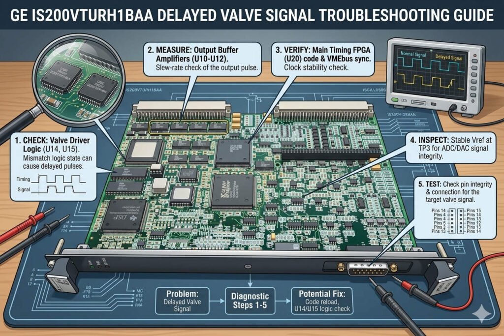
GE IS200VTURH1BAA Delayed Valve Signal Troubleshooting Guide
Resolving Delayed Valve Limit Switch Signals on GE IS200VTURH1BAA Modules
The GE IS200VTURH1BAA turbine control board manages critical valve open and close limit switch signals. When operators perceive these responses as “slow” within the HMI or control logic, hardware failure is rarely the cause. Instead, input filtering, contact bounce suppression, and scan-cycle coordination cause this apparent lag. In gas turbine, petrochemical, and compressor applications, this delay directly impacts valve permissive logic, startup sequencing, and trip response reliability. Therefore, engineers must understand the underlying system architecture to troubleshoot these latency issues successfully.
How Debounce Filtering Time Impacts Valve Position Status
Configured software filtering within the Mark VI or EX2100 I/O processing layer represents the primary cause of delayed software indications. Mechanical limit switches naturally produce transient chatter when contacts change state. To prevent false triggering, the controller applies filtering windows ranging from several milliseconds up to hundreds of milliseconds. In heavy-duty turbine auxiliary systems, engineers deliberately choose conservative debounce parameters to maximize stability. However, this strategy inadvertently delays the real-time visualization of factory automation status updates on operator screens.
Expert Insight from PLCDCS HUB: Many processing sites unknowingly inherit outdated debounce values from original commissioning templates. When you update field hardware without auditing the control logic, you create an avoidable bottleneck. At PLCDCS HUB, we advise reviewing these parameter baselines before condemning any field modules.
Analyzing Scan Cycle Synchronization Across Controller Networks
The GE IS200VTURH1BAA board routes valve status signals through the turbine control network, which introduces multiple processing layers. The signal must navigate the physical contact transition, the VTUR board acquisition, and the controller scan execution. In heavily loaded control systems with dense Sequence of Events (SOE) logging, this data path creates a noticeable lag. Consequently, actual control logic execution often occurs within milliseconds, while the HMI display updates up to two seconds later. Troubleshooting teams must separate actual logic delays from simple visualization refresh latency.
The Impact of Long Cable Runs and Contact Oxidation on Signal Edges
In massive refinery layouts, valve limit switches often operate 50 to 200 meters away from the main control cabinet. This extensive distance introduces high cable capacitance, which combines with oxidized dry contacts to degrade the signal edge. As a result, the VTUR input circuit interprets the slow-rising voltage transitions inconsistently during humid weather. Poor shield grounding and electrical noise further amplify these intermittent transition errors. For high-reliability applications, choosing gold-plated microswitches or proximity sensors minimizes these environmental degradation risks.
Essential Maintenance and Field Wiring Optimization Protocols
Optimizing discrete input performance requires structured installation practices and rigorous software verification steps. Field technicians should adhere to the following maintenance protocols:
- ✅ Review Software Constants: Check input filtering parameters inside ToolboxST before replacing any physical hardware.
- ✅ Deploy Shielded Cables: Use individually shielded twisted pairs to isolate limit switch wiring from high-current lines.
- ✅ Enforce Single-Point Grounding: Ground cable shields at one end only to prevent noise-inducing ground loops.
- ✅ Install Surge Protectors: Add DIN-rail surge suppressors near marshalling cabinets to block outdoor transient spikes.
- ✅ Verify Terminal Tightness: Inspect physical wiring terminations regularly to prevent vibration-induced signal dropout.
Procurement Strategies and Board Compatibility Guidelines
A slow-changing valve indication alone never provides sufficient justification to purchase a replacement VTUR board. Procurement managers should demand historical SOE logs and diagnostic alarm histories from maintenance teams first. True hardware failures typically manifest as entirely frozen input states, multiple channel failures, or persistent communication dropouts. When a replacement becomes necessary, remember that backward compatibility depends on specific firmware revisions and active redundancy architectures. Validating hardware revisions prevents unexpected commissioning stalls in your active PLC or DCS loop.
Application Scenarios and Solutions
- Gas Turbine Main Stop Valves: Eliminates false HMI transition alarms by tuning conservative software debounce windows.
- Petrochemical Bypass Systems: Restores precise SOE logging timestamps through the installation of high-purity gold-plated proximity switches.
- Offshore Compressor Stations: Safeguards sensitive VTUR input channels from marine lightning strikes using isolated surge barriers.
For genuine GE turbine control modules and comprehensive diagnostic support, visit PLCDCS HUB Limited today. We provide the certified components and engineering expertise required to maintain your industrial automation infrastructure.
Frequently Asked Questions (FAQ)
1. How do I prove that a slow valve signal stems from software configuration rather than hardware failure?
Compare the raw physical voltage change at the marshalling terminal against the SOE log timestamp. If the physical voltage drops instantly but the logic delays registration, the issue lies in your software debounce settings.
2. Will a standard industrial proximity switch work directly with the IS200VTURH1BAA input channel?
Yes, but you must verify that the proximity switch matches the excitation voltage provided by the GE terminal board. Additionally, update the input configuration parameters to reflect the lack of mechanical contact chatter.
3. What procurement details must I provide to ensure a replacement board functions immediately?
You must provide the exact suffix version of your current board along with the active system firmware revision. Mismatched FPGA baselines can prevent the Mark VI system from recognizing the new board during boot-up.