
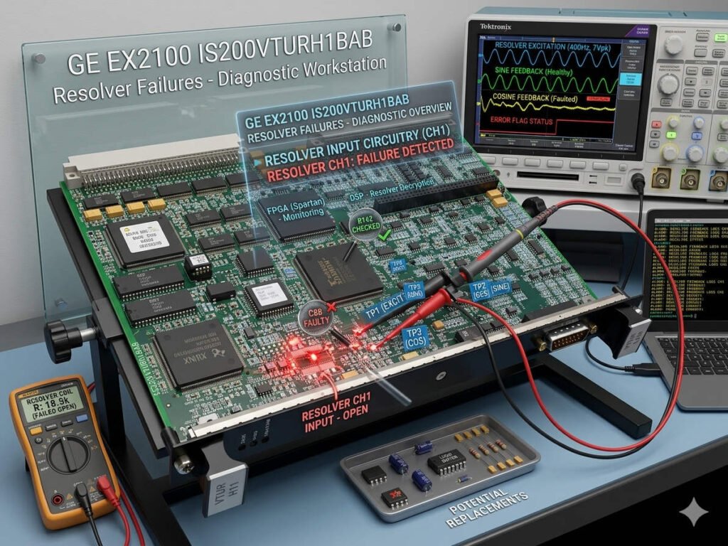
Troubleshooting IS200VTURH1BAB Resolver Failures in GE EX2100
Analyzing IS200VTURH1BAB Resolver Decoding Failures in Excitation Systems
The Critical Role of Resolver Decoding in Generator Synchronization
The IS200VTURH1BAB terminal board acts as the central intelligence hub for synchronization logic in GE EX2100 and Mark VI/VIe systems. This board interprets rotor position and phase-angle data to ensure safe grid connection. When the internal decoding circuit fails, the system loses its ability to track phase alignment accurately. Consequently, you may face synchronization rejections, reverse power alarms, or even severe torsional shock during breaker closure. Ensuring this circuit functions correctly is vital for protecting your generator shaft and maintaining grid stability.
Identifying Symptoms of Resolver Signal Instability
Engineers often overlook early warnings of decoding circuit degradation. However, experienced technicians can identify subtle shifts in performance before a complete system trip occurs. Watch for these common operational red flags:
- The sync check relay frequently refuses to close the breaker.
- AUTO SYNC functions oscillate wildly around the target frequency.
- Phase angle data shows inconsistent fluctuations during operation.
- The system generates repeated “25 Sync Check” alarm logs.
- Operators must resort to manual synchronization to bypass logic errors.
Diagnosing Resolver Feedback Challenges
Synchronization failures do not always stem from a faulty IS200VTURH1BAB board. Before you commit to a replacement, perform a thorough signal path audit to verify external conditions. Unstable feedback often results from environmental stressors or cabling issues rather than internal board defects.
- Verify the stability of the resolver excitation voltage using an oscilloscope.
- Check all cable shields to ensure you comply with IEC grounding standards.
- Inspect terminal blocks for oxidation or loose connections caused by vibrations.
- Confirm that your cabinet grounding resistance meets original design specifications.
Mitigating Environmental Impact on Control Electronics
Industrial environments pose significant risks to high-precision signal processing components. High humidity, extreme temperatures, and electromagnetic interference (EMI) accelerate the aging of interface ICs within the IS200VTURH1BAB. To improve the lifespan of your control systems, we recommend the following preventive measures:
- Install surge suppression modules if your site experiences frequent electrical noise.
- Use ferrule-terminated wiring to ensure reliable connections in high-vibration areas.
- Apply secondary cable restraints to protect feedback lines from mechanical fatigue.
- Maintain optimal cabinet cooling to prevent heat-induced diagnostic drift.
PLCDCS HUB Expert Perspective: Proactive Maintenance Strategy
At PLCDCS HUB, we frequently consult with plant operators who face synchronization instability during critical startup sequences. Reactive troubleshooting often wastes valuable maintenance windows and risks damaging your turbine-generator shaft. We advocate for a “predictive health” approach. By documenting phase angle trends during annual outages, you can replace aging hardware before it causes an unplanned trip. Visit PLCDCS HUB to access high-quality, tested replacement components that match your system’s specific hardware revision requirements.
Application Scenario: Resolving Synchronization Drift
In a recent case at a combined-cycle power plant, the control system rejected synchronization attempts due to intermittent resolver signal loss. The maintenance team initially suspected a faulty IS200VTURH1BAB board. However, our diagnostic review traced the issue to a micro-loose connector on the resolver cable inside a high-vibration turbine compartment. Securing the connector and cleaning the terminal points restored system stability immediately. This scenario demonstrates that meticulous physical inspection often resolves complex synchronization issues without requiring a full board replacement.
Frequently Asked Questions
- Q: How do I know if my synchronization instability is caused by the IS200VTURH1BAB board or the resolver sensor?
A: Use an oscilloscope to compare SIN/COS waveform symmetry. If the input signals at the terminal board are clean but the digital output is erratic, the decoding circuit likely requires replacement. - Q: Can I swap an IS200VTURH1BAB board with a newer revision if my current one is obsolete?
A: Compatibility depends on firmware and FPGA versions. Never assume direct plug-and-play capability. Check your I/O pack revision and configuration software before proceeding with any hardware changes. - Q: What is the most common cause of “Resolver Signal Loss” alarms in older Mark VI systems?
A: In our experience, grounding loops and shield drain miswiring are the primary culprits. Always ensure resolver cable shields are grounded at only one side to prevent circulating currents.