


Description
Product Overview
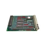
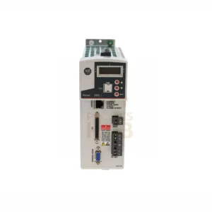
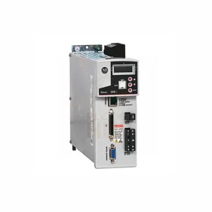
The GE DS200TCDAG1BDB is a Digital I/O Board. It belongs to the Mark V Speedtronic series. GE designed this board for steam and gas turbine control systems. The Mark V uses triple modular redundant (TMR) technology for high reliability.
What Makes This Board Special
- 12 relay channels for digital outputs
- Three product revisions – BDB version has all updates
- Hardware jumpers for flexible configuration
- IONET communication for fast data transfer
- Wide temperature range -30 to +65°C
Technical Specifications
- Brand: General Electric (GE)
- Model: DS200TCDAG1BDB
- Series: Mark V Speedtronic / Mark V LM
- Product Type: Digital I/O Board (TCDA)
- Functional Abbreviation: TCDA
- Power Requirements: +5V DC, 6 Amps
- Power Supply Voltage: 28V DC
- Relay Channels: 12
- Mounting: DIN rail
- Technology: Surface mount
- Operating Temperature: -30°C to +65°C
- Size: 15.9 cm (H) x 17.8 cm (W)
- Country of Origin: United States
- Repair Time: 3-7 days
- Availability: In Stock
- Manual: GEI-100182B
- Revision Quantity: 3 revisions
- Backwards Compatible: Yes, with first two revisions
Model Number Breakdown
- DS200 = General Electric Mark V series prefix
- TCDA = Functional abbreviation (Digital I/O board)
- G = Assembly type (Normal assembly)
- 1 = Revision number
- BDB = Specific revision with three product revisions
Hardware Features
- LED panel – shows board status at a glance
- Resistor network arrays – for voltage limiting
- Pin connectors – vertical plug type
- Integrated circuits – surface mount technology
- Capacitors and relays – for signal processing
- PCB coating – protects against wear and contamination
- Factory drilled holes – for easy mounting
- Alignment marks – along board edge for correct installation
Jumper Settings Guide
- J1, J8 – Factory testing only. Do not change.
- J2, J3 – IONET termination resistors
- J4, J5, J6 – IONET ID addressing. Leave at factory settings.
- J7 – Enables stall timer
- For complete jumper details, see Appendix A in the manual.
Connectors on This Board
- JP – Distributes power from TCPS board to Q11, Q21, Q51 cores
- JQ – Connects to DTBA board for contact input signals
- JR – Connects to DTBB board for contact input signals
- JO1 – Sends relay signals to TCRA board (location 4)
- JO2 – Sends relay signals to TCRA board (location 5)
- JX1 – Shielded cable for IONET signals to TCEA board
- JX2 – Same function as JX1 (use either port)
How This Board Works
- It manages digital contact input signals from DTBA and DTBB boards.
- It handles contact output signals (relays and solenoids) from TCRA boards.
- Signals travel through the IONET network.
- The board works inside the Mark V R1 core.
- Software configuration uses the HMI I/O Configuration Editor.
- Set contact input inversions through the software.
Compatible Boards in the Same Core
- TCEA
- TCQE
- TCQA
- UCPB
- STCA
Installation Guide
- Mount on DIN rail in the correct core (Q11, Q21, or Q51).
- Use alignment marks along the board edge.
- Secure with factory-drilled mounting holes.
- Connect JP for power distribution.
- Attach JQ and JR for input signals from DTBA and DTBB.
- Connect JO1 and JO2 for output signals to TCRA boards.
- Use JX1 or JX2 for IONET communication.
- Verify jumper settings before powering on.
- Refer to manual GEI-100182B for full details.
Configuration Tips
- Set hardware jumpers J4-J6 for IONET ID. Leave at factory defaults.
- Enable stall timer with J7 jumper if needed.
- Use HMI I/O Configuration Editor for software settings.
- Input constants for contact input inversions via software.
- No DIP switches – all software controlled.
Maintenance & Diagnostics
- Check LED panel for board status.
- Monitor MODULE OK indicator during operation.
- Use IONET diagnostics through the operator interface.
- The board reports faults via the Mark V alarm system.
- Replace board if relay channels fail or IONET drops.
- Keep PCB coating intact – do not scratch.
Compatibility Notes
- Works with Mark V Speedtronic turbine control systems.
- Compatible with DTBA and DTBB terminal boards.
- Works with TCRA boards for relay outputs.
- Backwards compatible with first two revisions of TCDA board.
- Use with TCEA, TCQE, TCQA, UCPB, STCA in same core.
Typical Applications
- GE steam turbine control systems
- GE gas turbine control systems
- Digital contact input monitoring
- Relay and solenoid output control
- Industrial power generation plants
Diagnostic Capabilities
- IONET communication status monitoring
- Contact input signal verification
- Relay output channel testing
- Stall timer status check
- Power supply voltage monitoring (28V DC, 5V DC)
Warranty & Shipping
- 12 months warranty from delivery date.
- Covers manufacturing defects only.
- Does not cover wrong jumper settings or improper installation.
- We ship by FedEx, UPS, or DHL.
- Tracking number provided after dispatch.
Package List
- 1 x DS200TCDAG1BDB Digital I/O Board
- No cables or connectors included (sold separately)
- Manual available as PDF upon request (GEI-100182B)
Professional FAQ
- What is the difference between DS200TCDAG1 and DS200TCDAG1BDB?
- The BDB version has three product revisions. The original TCDAG1 does not have these updates. BDB is more advanced.
- Can I use this board with Mark VI or Mark VIe systems?
- No. This board works only with Mark V Speedtronic systems. Check your system version before buying.
- Experience: My IONET communication keeps failing. What should I check?
- Check jumpers J2 and J3 for termination resistors. Also verify J4-J6 IONET ID settings. Wrong addressing causes communication loss.
- Experience: One relay channel stopped working. Is the whole board bad?
- Not necessarily. Other channels may still work. Replace the board if the failed channel is critical. We have spare boards in stock.
- Buying guide: Do I need the BDB revision or can I use older TCDA boards?
- Use BDB for new installations. It has all three revisions. Older boards may lack features. BDB is backwards compatible with older revisions.
- Buying guide: How many relay channels do I need for my turbine?
- Count your solenoids and relays first. This board has 12 channels. Use multiple boards if you need more outputs.
- Buying guide: What power supply do I need for this board?
- You need +5V DC at 6 Amps and 28V DC supply. The Mark V rack usually provides these. Verify before connecting.
- Can I configure jumpers without the manual?
- No. Always use Appendix A in manual GEI-100182B. Wrong jumper settings may damage the board or connected devices.
For questions or orders, contact us: +86 158 8020 0923 (WhatsApp)
Copyright © 2026 PLCDCS HUB Limited. All rights reserved.
Original Source: https://plcdcshub.com/
Partner: Powergear X Automation Limited
Oiltech Controls Limited


0.0 Average Rating Rated (0 Reviews)