RS-422 Encoder Wiring Tips for Industrial Control Systems
Reliable Interfacing of Line Driver Encoders with PLC Control Systems
Interfacing differential line driver encoders with standard PLC digital inputs poses a common challenge in industrial automation. While line drivers (RS-422) provide superior noise immunity, most standard PLC inputs use single-ended logic. Misalignment between these signals often causes missed pulses or hardware damage. Therefore, engineers must ensure signal compatibility to maintain positioning accuracy. Proper integration stabilizes counting and improves overall product quality in high-speed environments.
Bridging Differential Signals and Single-Ended PLC Inputs
Line driver encoders output differential signals to cancel out common-mode noise. Conversely, standard PLC DI channels typically expect a single-ended PNP or NPN signal. If you connect only the A+ lead to a standard input, signal integrity suffers. As a result, electromagnetic interference (EMI) causes pulse loss over long distances. This leads to cumulative errors in cutting machines or conveyor systems. PLCDCS HUB recommends using an RS-422 to PNP/NPN converter for consistent data.
Optimizing Response Frequency for High-Speed Logic
Standard control systems often feature digital inputs designed for simple switch logic. These inputs typically have response times between 5ms and 20ms. However, encoder pulses in factory automation frequently reach the kilohertz range. If the pulse frequency exceeds the input capability, the PLC fails to register the movement. This mismatch causes significant positioning drift and inaccurate speed feedback. Always verify that your hardware supports the maximum pulse frequency of your application.
Enhancing EMI Immunity for Long-Distance Transmission
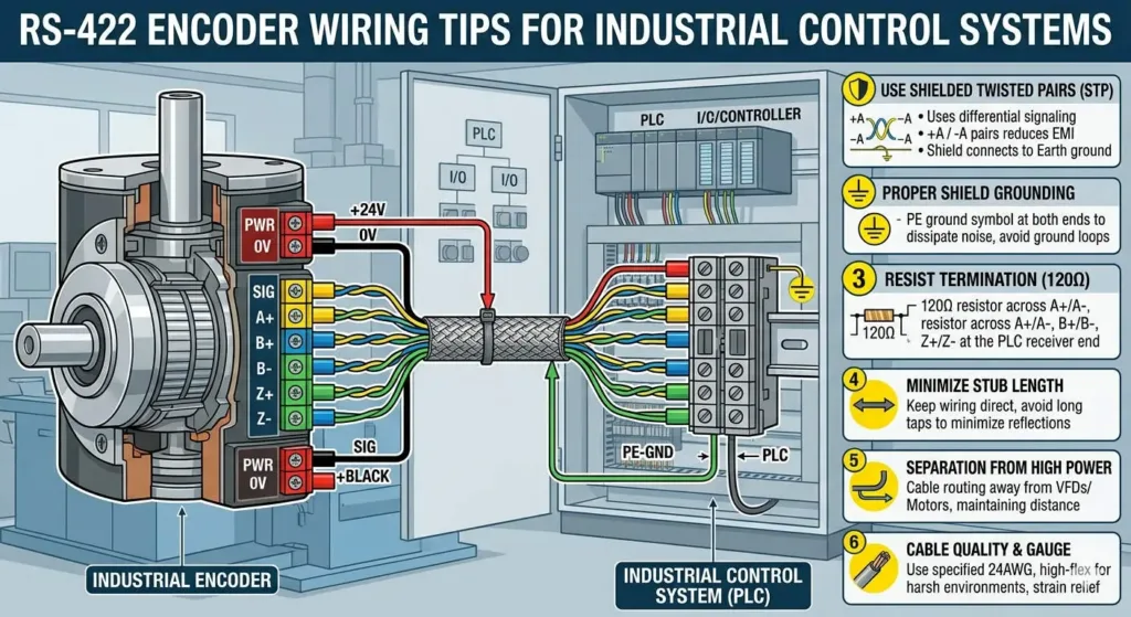
Differential encoders excel in environments with long cable runs up to 300 meters. These areas often contain high-power motors and VFDs that generate substantial noise. Using a single-ended connection negates the inherent anti-noise advantages of the line driver. Therefore, maintaining the differential pair is vital for system reliability. Moreover, adding a 120Ω termination resistor helps prevent signal reflection on long lines. This approach reduces downtime caused by intermittent signal faults.
Expert Insight from PLCDCS HUB: In my decade of managing DCS operations, I have seen many quick fixes fail. Technicians often bypass signal converters to save time during commissioning. However, the resulting jitter usually forces a costly shutdown later. Professional signal matching is a technical requirement, not a luxury.
Technical Best Practices for Installation and Shielding
Proper installation prevents most encoder-related errors before they start. Follow these engineering guidelines to ensure long-term stability:
- ✓ Use Signal Converters: Install differential-to-single-ended modules for standard DI cards.
- ✓ Shielded Wiring: Always use shielded twisted-pair cables for signal pairs.
- ✓ Single-Point Grounding: Ground the cable shield at the PLC side only.
- ✓ Cable Separation: Keep signal lines at least 20cm away from power cables.
- ✓ High-Speed Modules: Use dedicated High-Speed Counter (HSC) modules for motion tasks.
Buyer’s Guide for Encoder Hardware Upgrades
Deciding when to upgrade your hardware depends on several factors. First, evaluate your required precision. If your application involves synchronized cutting or high-speed sorting, standard DI is insufficient. Second, check your signal standards. If your encoder uses RS-422, a direct connection to a 24V DC input will likely fail. Finally, consider the environment. Heavy industrial zones require the robust protection offered by dedicated differential input modules.
Frequently Asked Questions (FAQ)
1. Can a 24V PLC input handle a 5V line driver signal?
No, most line drivers operate at 5V. A 24V PLC input will not see the 5V signal reliably. You must use a level shifter or a compatible high-speed counter module.
2. Why does my encoder count jump randomly when the motor starts?
This is likely EMI noise leaking into the signal line. Ensure you use differential signals and ground your shielding at only one end.
3. When should I choose a dedicated high-speed counter module?
Choose a dedicated module whenever the encoder frequency exceeds 100Hz. Standard PLC scan cycles are too slow to track high-speed industrial pulses accurately.
Explore our full inventory of high-speed modules and interface solutions at PLCDCS HUB Limited. We provide the technical components needed to secure your industrial data integrity.
Related Posts


No Comments