Troubleshooting ABB PC D230 3BHE022291R0101 Fiber Optic Errors
Troubleshooting ABB PC D230 3BHE022291R0101 Fiber Optic Rx Power Low Alarms
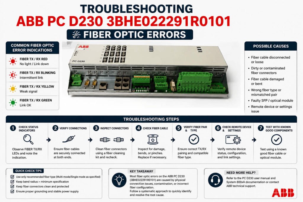
The fiber optic communication interface on the ABB PC D230 3BHE022291R0101 bus board provides high-speed, deterministic data exchange between DCS subsystems. When the system triggers a “Rx Power Low” alarm, it does not always point to a hardware defect. In many refinery and petrochemical facilities, gradual optical attenuation or connector contamination causes this issue. For process industries, accurate root-cause identification prevents incorrect part replacements. Furthermore, isolating the exact cause avoids costly communication dropouts and unstable controller redundancy switches.
Optical Receive Threshold Stability and DCS Reliability
The communication channel generates the “Rx Power Low” alarm when received optical power drops below a strict sensitivity threshold. In ABB Symphony and UNITROL architectures, this threshold features narrow margins to maintain precise network timing. Consequently, when optical power fluctuates near the limit, intermittent communication CRC errors often disrupt the system. Sporadic I/O timeout events may also occur during periods of high electromagnetic interference. Experienced engineers know that maintaining stable receive power is more vital than achieving high peak optical power.
Expert Insight from PLCDCS HUB: We frequently see plants replace expensive communication boards prematurely. Over 50% of fiber alarms stem from minor physical defects or poor cabinet conditions rather than a dead transceiver circuit. Always isolate the physical cable infrastructure before condemning the high-value silicon on your control systems.
Differentiating Fiber Aging from Damaged Interfaces
Aged optical fibers typically display a slow, progressive increase in signal attenuation over several months or years. Long-term bending stress, heat exposure in cable ducts, and micro-cracks from routing modifications accelerate this degradation. Conversely, a damaged physical interface on the board triggers an abrupt, persistent drop in optical power. Cleaning the connectors yields no improvement if the internal receiver circuitry suffers from ESD or failing solder joints. Swapping ports helps determine whether the fault follows the cable path or remains fixed on the board.
The Impact of Extreme Environmental Cabinet Conditions
Harsh cabinet environments heavily influence the lifespan of optical transceivers and interconnects in factory automation loops. Continuous operation above 45°C accelerates laser diode aging and induces power drift within the optical circuitry. Additionally, continuous mechanical vibration near gas turbine skids can gradually loosen ST or SC connectors, increasing insertion loss. Poor cabinet grounding also introduces transient disturbances into communication lines during heavy motor startups. Therefore, technicians must maintain proper shielding continuity according to IEC 61000 standards.
Field-Proven Maintenance Protocols and Optical Diagnostics
Isolating communication faults on the PC D230 board requires a structured, multi-step engineering approach. Maintenance teams should execute the following technical steps:
- ✅ Trend Comparison: Compare current Rx readings against historical power logs to identify gradual fiber attenuation.
- ✅ Port Swap Testing: Connect a known-good short jumper between ports to see if the alarm remains fixed.
- ✅ Microscopic Inspection: Examine connector end-faces under magnification to identify hidden airborne dust or oil films.
- ✅ Chemical Cleaning: Clean contaminated optical tips using lint-free swabs and isopropyl alcohol to restore power.
Procurement Strategies and System Compatibility Guidelines
Only purchase a replacement PC D230 board after confirming that the existing fiber optic cable passes attenuation testing. When sourcing a new board, remember that backward compatibility depends on firmware revisions and optical wavelength budgets. Mixing different generations of optical assemblies without calculating the attenuation margin can introduce network jitter. Buyers must verify whether the existing architecture utilizes multimode or single-mode fiber types. This diligence ensures seamless field integration into your active PLC or data highway network.
Application Scenarios and Solutions
- Refinery Turbine Control Skids: Eliminates intermittent I/O timeout errors by stabilizing loose fiber connections subjected to continuous vibration.
- High-Temperature MCC Rooms: Prevents laser power drift failures by optimizing enclosure cooling and replacing degraded optical boards.
- Offshore Production Networks: Restores reliable controller redundancy tracking by cleaning salt-crusted fiber connectors during scheduled turnarounds.
For authentic ABB communication modules and professional technical diagnostics, visit PLCDCS HUB Limited today. We provide the certified parts and industrial insight needed to protect your industrial automation investments.
Frequently Asked Questions (FAQ)
1. What optical power reading indicates a critical failure on the PC D230 receiver?
While specific budgets vary, readings dropping below -22 dBm usually trigger the low power alarm. If a known-good patch cable yields the same low reading, the board transceiver has likely degraded.
2. Can I use standard consumer cleaning wipes on industrial ABB fiber connectors?
No, consumer wipes often leave lint residues or static charges that attract dust inside the enclosure. Always use specialized, lint-free optical cleaning swabs paired with high-purity isopropyl alcohol.
3. Why did my low power alarm disappear temporarily after I wiggled the fiber cable?
This symptom points to either a loose connector lock or excessive bending stress near the cabinet door hinge. Secure the cable with proper strain relief clips to prevent permanent fiber micro-cracks.