PLC I/O Point Calculation Guide for Industrial Control Systems
Mastering I/O Point Calculation for PLC and DCS System Design
The Strategic Role of Accurate I/O Mapping
Precision in I/O point calculation remains a cornerstone of industrial automation success. Inaccurate estimates often trigger expensive hardware retrofits or cabinet expansions during the commissioning phase. Therefore, engineers must treat I/O sizing as a critical financial and technical constraint. Proper planning ensures seamless scalability in sectors like oil and gas or chemical processing. At PLCDCS HUB, we observe that over-designing leads to wasted capital, while under-designing halts project momentum.

Distinguishing Between Digital and Analog Signals
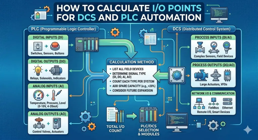
Effective system architecture begins with a clear classification of field signals. Digital I/O (DI/DO) handles discrete data such as limit switches and solenoid valves. Conversely, Analog I/O (AI/AO) manages continuous variables like pressure and flow via 4–20 mA loops. Precision is vital here because analog cards cost significantly more than digital ones. Moreover, high analog density increases CPU overhead and can degrade critical scan times. Systems in complex processing plants require meticulous module planning to maintain high-speed control loops.
Optimizing Module Density and Hardware Capacity
Standard I/O modules typically offer densities of 8, 16, or 32 channels. Engineers must calculate the total card count by dividing the field device list by these capacities. However, a common mistake is filling every available slot during the initial design. PLCDCS HUB Limited experts recommend a 15% to 20% spare capacity buffer. This strategy accommodates late-stage safety interlocks or extra sensors without requiring new racks. Without this margin, simple field additions can cause significant project delays and cabinet redesigns.
Remote I/O Integration and Network Constraints
Modern distributed architectures rely heavily on remote I/O via EtherNet/IP or PROFINET. While this reduces wiring costs, it introduces communication latency variables. Each remote station still contributes to the total system I/O count and consumes network bandwidth. Consequently, placing too many points on a single segment may destabilize time-critical PID loops. We suggest balancing the load across multiple network switches to ensure consistent data refresh rates. Robust network design is just as important as physical hardware selection.
Essential Installation and Maintenance Standards
Long-term reliability depends on disciplined installation habits and high-quality documentation. Labeling every wire with ferrules and matching tags to P&ID diagrams saves countless troubleshooting hours. Additionally, hardware in outdoor or high-noise environments requires specialized protection. We strongly advise using signal isolators and surge protectors to shield sensitive input cards from lightning or VFD interference. At PLCDCS HUB, we believe that preventive hardware shielding is a mandatory investment for industrial uptime.
Expert Insights from PLCDCS HUB
The transition toward Industry 4.0 demands more intelligent I/O solutions. We see a growing trend where users move from traditional rack-based I/O to decentralized, software-defined modules. This flexibility allows for faster re-configuration without changing physical wiring. When selecting spare parts or expanding existing systems, always prioritize compatibility with legacy backplanes. Our team at PLCDCS HUB Limited specializes in sourcing high-end modules from ABB, Honeywell, and Allen-Bradley to keep your systems running efficiently.
Technical Implementation Checklist
- Identify all DI, DO, AI, and AO field points correctly.
- Calculate module requirements based on standard channel densities.
- Allocate 20% spare channels for future system expansions.
- Verify CPU scan time impact for analog-heavy applications.
- Implement surge protection for all outdoor field instruments.
- Ensure documentation matches the physical I/O mapping exactly.
Industrial Application Scenarios
In a recent chemical dosing project, the use of remote I/O reduced cable costs by 30%. By implementing 15% spare AI channels, the client integrated three additional safety transmitters during startup without hardware changes. Similarly, in large-scale manufacturing, using high-density 32-point DI modules saved significant cabinet space. These scenarios prove that proactive I/O calculation directly supports project deadlines and budget control.
Frequently Asked Questions (FAQ)
Q: How do I determine if my current PLC can handle more I/O modules?
A: You must evaluate three factors: physical rack space, CPU memory limits, and power supply capacity. Check the manufacturer’s maximum I/O image size to ensure the processor can address new points. If the scan time exceeds your process requirements, consider upgrading the controller or offloading tasks to a secondary PLC.
Q: What are the risks of mixing different hardware generations in one system?
A: Mixing generations often leads to firmware conflicts or intermittent communication drops. While some backplanes support older cards, specific features like “hot-swapping” might not function correctly. Always consult a specialist to verify the revision compatibility between your CPU and the new I/O cards.
Q: Should I use terminal blocks even for unused I/O channels?
A: Yes, pre-wiring unused channels to terminal blocks is a best practice. This allows maintenance teams to add new devices quickly without touching the sensitive PLC card wiring. It reduces the risk of accidental short circuits and speeds up emergency repairs in active production environments.
For high-quality industrial automation spare parts and expert technical support, visit the PLCDCS HUB Limited official website at https://plcdcshub.com/ to browse our extensive inventory of PLC and DCS components.
Related Posts


No Comments