Bently Nevada 3500/42M Guide: Mastering Gap Voltage Diagnostics
Mastering Gap Voltage Diagnostics with the Bently Nevada 3500/42M Proximitor Monitor
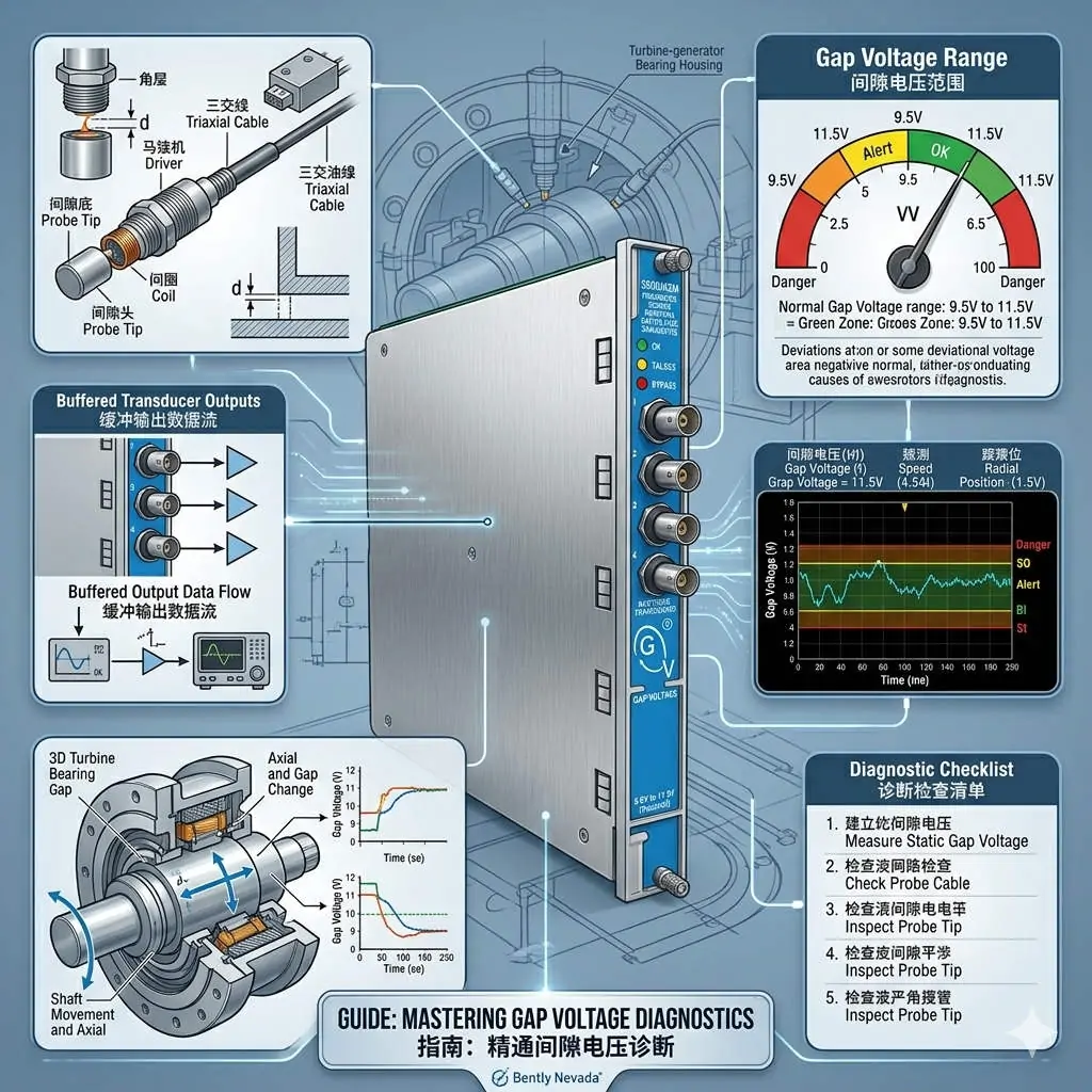
In the world of industrial automation and machinery protection, the Bently Nevada 3500/42M module plays a pivotal role. The “Gap Voltage” signal serves as the primary health indicator for the entire proximity probe chain. This chain includes the probe, extension cable, and the Proximitor sensor. Accurate gap readings ensure reliable shaft position monitoring and vibration measurement. Consequently, maintaining this signal prevents false alarms and protects high-value assets in oil, gas, and power plants.
Understanding the Mechanics of DC Gap Voltage
Gap Voltage represents the physical distance between the probe tip and the target shaft surface. Typically, this value ranges from -24V to -8V DC. A voltage that is too high (less negative) suggests the probe is too far away. Conversely, a low voltage (more negative) indicates the probe is too close. Incorrect gapping distorts vibration data and masks critical faults like shaft misalignment. Therefore, precision in setting the initial DC offset is vital for long-term machine reliability.
Ensuring System Linearity and Calibration Matching
The 3500/42M relies on a perfectly matched set of components to maintain measurement integrity. Each probe, cable, and Proximitor must share the same electrical length and calibration. Mixing different models or cable lengths breaks the system’s linearity. PLCDCS HUB frequently observes field errors where engineers replace only one component without verifying the set. As a result, the system reports abnormal voltages despite correct physical installation. Always verify that your hardware matches the factory calibration curves.
Combatting Signal Noise and Electrical Interference
Sensitive monitoring circuits often face challenges from electromagnetic interference (EMI). High-power motors and Variable Frequency Drives (VFDs) can induce noise into the proximity signal. Poor shielding or improper grounding creates voltage fluctuations that trigger intermittent alarms. These nuisance trips increase maintenance costs and decrease operator trust. To ensure stability, engineers must adhere to strict API 670 standards for cable routing and cabinet isolation.
Practical Maintenance Strategies for Field Engineers
Effective maintenance requires a systematic approach rather than guesswork. Our team at PLCDCS HUB Limited recommends following these technical steps for every installation:
- ✅ Mechanical Verification: Use a feeler gauge to set the physical gap during commissioning.
- ✅ Component Inspection: Check probe tips for oil contamination or metal debris regularly.
- ✅ Thermal Checks: Re-verify Gap Voltage after the machine reaches operating temperature.
- ✅ Grounding Integrity: Maintain single-point grounding to prevent destructive ground loops.
Buyer’s Guide for 3500/42M System Components
When Gap Voltage becomes erratic, do not assume the 3500/42M module is faulty. Field data suggests that over 70% of issues originate in the field-side cabling or probes. First, validate the probe system with a portable calibrator. If multiple channels show the same error, then investigate the monitor rack. For legacy upgrades, remember that the 3500 series requires specific firmware versions to support newer Proximitor models. Always consult a specialist to ensure full system compatibility.
Expert Insight from PLCDCS HUB: We see a rising trend in high-temperature environments causing cable insulation decay. This degradation often manifests as a slow “voltage drift” over several months. Proactive replacement of extension cables can prevent catastrophic monitoring failure.
Application Scenarios and Industry Solutions
- Gas Turbine Protection: High-speed monitoring of axial thrust and radial vibration.
- Centrifugal Compressors: Detection of early-stage surge conditions via shaft position shifts.
- Hydroelectric Power: Reliable monitoring in high-moisture environments using specialized probe housings.
For high-quality Bently Nevada components and expert technical guidance, visit PLCDCS HUB Limited. We provide the authentic parts and DCS solutions your facility needs to stay operational.
Frequently Asked Questions (FAQ)
1. Why does my Gap Voltage change when the machine starts up?
Thermal expansion causes the machine shaft to shift physically. This movement changes the distance to the probe, thus altering the DC voltage. You should document these “hot” versus “cold” offsets for future reference.
2. Can I use a 5-meter probe with a 9-meter extension cable?
No, this will cause severe calibration errors. The Proximitor is tuned for a specific total electrical length (usually 5m or 9m). Mismatched lengths lead to non-linear vibration readings and incorrect gap indications.
3. How do I choose between the 3500/42M and the 3500/40M?
The 3500/42M is the “Proximitor” monitor specifically for proximity probes. The 3500/40M is typically for seismic sensors like accelerometers. Always choose the module that matches your specific sensor type to comply with API 670 requirements.
Related Posts


No Comments